Module 2 - Wiring Loom
Module 2 Build:
<16th September 2005>
 Wiring Loom Installation:
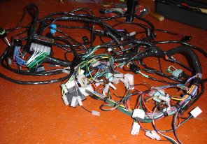
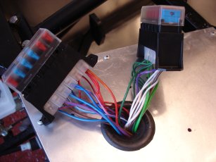
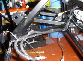
As you can see from the picture the loom is rather large and fairly messy when you first get it out of the packaging. However once its carefully unravelled there are 2 main sections, the fuse boxes and the dashboard connections. Once these 2 are seperated there are 2 tail ends one goes to the front for the headlights and horn, etc.. and the other goes to the back for all the rear light and fuel pump, etc...
So the first thing to do is lay the loom out roughly where it will go and then move onto locating the individual parts more permanently.
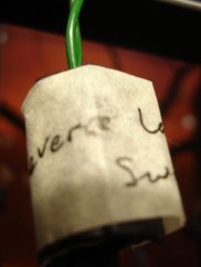
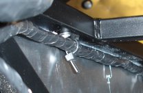
This leads to the fuse boxes, which are the first things to locate and attach in their place. To do this though you have to take all the connections off the fuse boxes and reconect them after feeding them through the hole in the scuttle panel. To make sure i got the cables back in the correct places i followed the instructions in the manual and labelled each slot in the fuse box and then each cable as i took them out with a matching number. You may be able to see it in the picture below but i only had a pencil to hand so it didn't stand out very well. All in all a simple process though.
<18th September 2005>
Only popped over for an hour today but managed to get the other fuse box through the hole in the scuttle and connected to the fixings. I followed the same approach as the initial fuse box to lable the connections. Then once through and re connected i was able to pull the rubber protecting ring through and position it in the scuttle hole. The next problem was to fit the fuse boxes to the scuttle alloy panel. It says to use M5 x 25mm setscrews but holes in both the fuse boxes and the alloy are considerably smaller then that, i found an M4 was a good fit through the fuse box but i needed to drill out the holes in the allow slightly to fit them through there. Luckily i has some and so i could fit them ok, one piece of advice though, the 10mm aluminium spacers were in a "generic" bag so i had to hunt for them.
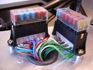
 Once they were in place though it give the loom its initial position which allowed me to trace a route around the chassis rails for it to sit. After i'd roughly set it out i cable tied the front part of the loom with the radiator fan connection in the center of the top front chassis rail.
 I now plan to go through the less obvious sockets and label them up with pen on masking tape so i don't have to keep refering to the wiring manual, "red/black with blue/green oh yeah thats number 23 the left indicator warning light" could soon get confusing!
I plan to attach the loom mid section to the top chassis rail through the transmittion tunnel but apart from that i will leave the final cable tying until most things are in place and i'm confident i wont have to move it!
<20th September 2005>
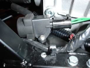
First thing i did was to get the transmittion tunnel alloy panel and start feeding the loom through the hole that was pre cut for it. There is another rubber ring to go around this hole i could tell from that how much of the cable needed to be fed through. The first problem was that the hazard warning switch wouldn't fit through the gap so i had to unplug it and then plug it back in the other side. This was straight forward enough until i got the bottom part of the loom.
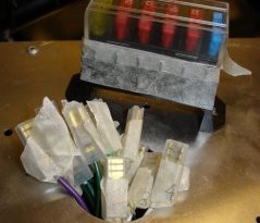
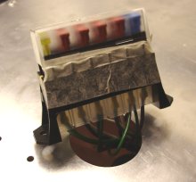
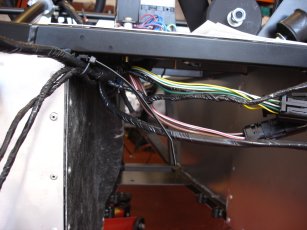
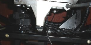
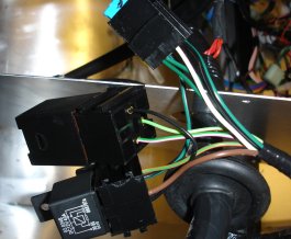 As you can see from the picture there are a bunch of relays near the rubber ring that would not fit through with the cable in the hole. This left me with two choices, i either strip the wires from the sockets and then feed it through and re-wire it the other side, or the option i chose which is to leave it as it is for now and when it comes time to fit the transmision tunnel cover or the loom then i will cut a line to the hole and slip the cable through it. Once tne panel is rivetted on to the chassis there will be very little room for it to move. For now i just needed it out of the way so i could go about routing the rest of the loom. But you can see from the pic below roughly how it will look with the transmission cover in place.
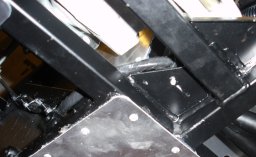
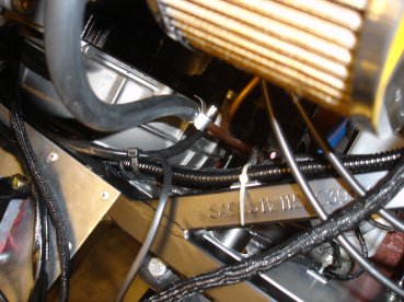
Once that bulk was out the way i plotted my route for the rear loom through the top chassis rail in the tunnel. It then slots through at the side just above the diff and follows a simple route around the chassis rails at the rear. To keep it tidy and in place i used the P Clip style cable tie adapters riveted into the chassis at the top. I wanted to get this in place as now all is clear for the gearbox to fit through.
After recieving an e-mail from a fellow westfield builder Pete who has been checking this site i tried his recommended approach to fitting the dashboard loom section through the transmission panel. He suggested that it is possible to fit the whole loom through without the need to cut the panel at all. It basically involved putting the large relays through the hole first and then slowly feeding the rest of it through. This made sense but it seemed a bit impractical due to having to almost fold the loom. This was not the case at all though and following this approach i was easily able to get everything through! So thank you Pete, i now have a nice and neat loom with the rubber ring in place protecting the cables from the rather sharp alloy.
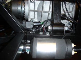
I found the smaller seperate section of the loom that had connectors to join the main loom round about the main fuse box area. This contained the Starter Motor cables, Radiator fan switch and the like. I think these will all sit on the left hand side of the car so i was able to roughly route them under the front chassis rail as in the picture below. Now i had located the positions the different braches of the loom would sit i drilled a couple more hole and riveted in some cable tie holders to secure the cables. This should mean i can keep everything out of the way during the engine install.
<18th October 2005>
As I have fitted all the fuel hoses in place to the rear of the chassis i decided to locate the rear loom in it's final position and fasten it all down. I spent a long time looking at where to route the initial securing rivits to keep the loom away from the hand brake cables, the solid brake lines, and the sharp edge of the alloy panels.
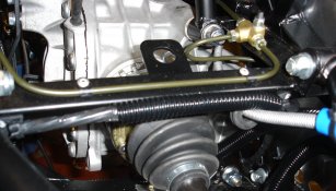
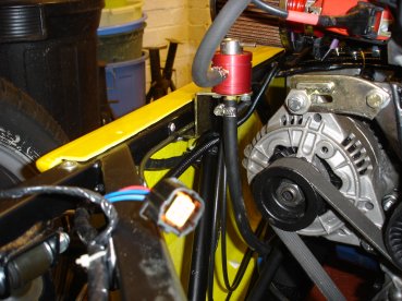
I made a decision to go back a step from where i had left it before and run the cables down the rear diagonal chassis rail in the transmittion tunnel. This would allow me to run the loom along the bottom and keep it away from all the other pipes and cable which run at the top exit of the tunnel. As you can see from the pictures below it kept the arrangement very clean
From there i routed it straight up and attached a cable tie rivit to the outside edge of the chassis rail above the drive shaft. To protect this from the handbrake cable i covered this part in some of the flexible plastic hose. From there i then routed down and along the far right rear corner for the rear right light clusted.
Doubling back and using the same cable ties to fix it in place i took the rest back and up through behind the diff, riveting a couple of fixings along the top of the lower chassis rail there. Then fix the left hand cables down the rear left chassis rail.
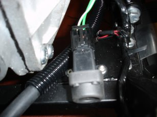
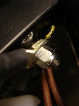
This just left the locating of the Fuel Inertia cut off reset switch. I was trying to find a nice and neat location to fit this and make sure it was still accessible without having to remover all the boot. I have seen lots fitted on the right at the back behind the diff but this seemed to interfere with the fuel pipes and loom fixings. So i decided to fasten it to the left behind the diff, this way its accessible through the left suspension, and yet it out of the way of all wires, hoses, and pipes.
<2nd February 2006>
 Copyright ©2012
Kevin Baldwin
Copyright ©2012
Kevin Baldwin